
Page 1 of 2
| Differences between types of track circuits? 13/12/2011 at 23:39 #25392 | |
|
maxand
1637 posts |
I understand what track circuits (TCs) are for and how they work, but what's the difference in SimSig between the ones that look like a horizontal T and others that have no bar at the end? How does that translate to real life? Thanks for explaining. Last edited: 13/12/2011 at 23:41 by maxand Log in to reply |
| Re: Differences between types of track circuits? 13/12/2011 at 23:40 #25393 | |
|
jc92
3738 posts |
overlap TCS
"We don't stop camborne wednesdays" Log in to reply The following user said thank you: maxand |
| Re: Differences between types of track circuits? 13/12/2011 at 23:55 #25414 | |
|
Lardybiker
771 posts |
" said:I understand what track circuits (TCs) are for and how they work, but what's the difference in SimSig between the ones that look like a horizontal T and others that have no bar at the end? How does that translate to real life?The ones looking like a 'T' is an overlap. An overlap is one or more protective TC's beyond a signal. Its typically 183m in a multi-apsect signalling system but that not a hard or fast rule. Last edited: 13/12/2011 at 23:56 by Lardybiker Log in to reply The following user said thank you: maxand |
| Re: Differences between types of track circuits? 14/12/2011 at 00:00 #25418 | |
|
maxand
1637 posts |
I get it now, thanks, should have put two and two together.
Log in to reply |
| Re: Differences between types of track circuits? 14/12/2011 at 06:34 #25435 | |
|
Peter Bennet
5437 posts |
And the TCs where the O/L marker is on the same TC as the Signal mean the TC extends beyond the signal rather than as a separate TC. I don't know what dictates the rule there but more often it's automatic signals that have the integral TCs. Peter I identify as half man half biscuit - crumbs! Log in to reply |
| Re: Differences between types of track circuits? 14/12/2011 at 10:05 #25440 | |
|
kbarber
1779 posts |
" said:And the TCs where the O/L marker is on the same TC as the Signal mean the TC extends beyond the signal rather than as a separate TC. I don't know what dictates the rule there but more often it's automatic signals that have the integral TCs. In my experience (admittedly little that's up-to-date) a single TC covering both section and overlap is invariably in an auto section. Originally, separate TCs would typically be provided for section and overlap. I imagine signal engineers assumed the same should apply to autos as to controlled signals, and that a signal should not be left standing clear for a second or so until the train got to the end of the overlap. By the 1960s (I think), although separate overlap TCs were still provided, they no longer had separate indications in the box; rather, there was one "TC" indication covering the overlap at the rear end of the section, the signal section itself and the overlap beyond the signal at the advance end. In other words the overlaps were shared between the two signal section indications they related to. This was the situation at Marylebone (the 1967 box), where the section to Neasden South had the first "daylight" multiple-aspect colour lights on a British main line (commissioned 1923); the age of the installation (I believe they used three-position relays!) resulted in some interesting behaviour, with TC indications flashing momentarily behind a train. Neasden South retained its original diagram; not only was each TC indicated separately, but the indications were "lit when clear" white lights, with an occupied TC going dark - a real trap for the unwary. By the 1970s it seems to have been realised that there was no point having a separate overlap TC; it really didn't matter if a signal remained clear until the train reached the end of the overlap, because no train could approach it in any case as the signal in rear would be held at danger until the overlap became clear. Log in to reply The following user said thank you: maxand |
| Re: Differences between types of track circuits? 14/12/2011 at 10:46 #25446 | |
|
maxand
1637 posts |
One more dumb question about overlaps: In SimSig, certainly, trains never overshoot their signals and the overlap TC is released as soon as the train stops. All very nice, but in real life what determines the release of the overlap TC? Obviously something knows the train's stopped, and it's not the signaller. Is the overlap track section released after a fixed interval if the train hasn't overshot (which sounds dangerous to me) or is there some device that senses when the train has come to a stop (before the signal), and then releases the overlap, enabling further routes to be set? If the latter is the case, then is this information (that the train has come to a standstill) transmitted to the signaller, so he can be absolutely certain? Just wondering... :whistle: PS I googled around a bit before posting this question here. Plenty of sites explain what overlap is, but none of them seem to go into the gritty details of how this happens. Last edited: 14/12/2011 at 11:11 by maxand Log in to reply |
| Re: Differences between types of track circuits? 14/12/2011 at 10:55 #25447 | |
|
GeoffM
6420 posts |
" said:One more dumb question about overlaps:In real life the berth track circuit (the last approaching a signal) starts timing once occupied. When it's been occupied for a pre-calculated time, the overlap drops. That pre-calculated time involves a signal design engineer working out how long it will take for a typical train to occupy that track and come to a stand. That same method is used in SimSig, by calculating how long it might take, but as the logic for calculating an overlap release time is the same as for an actual simulated train, it often looks like the sim releases the overlap when the train stops. This is not the case. Try it without a train (F11/ICP). More recent sims might have some overlap release times taken from real life. It depends how much information we can get hold of. If the developer doesn't specify it in data then the sim calculates it automatically. In real life, unless the signaller can see the train or has spoken to somebody who can see the train (eg driver), he has no way of knowing whether it is actually stopped or simply crawling along towards the signal at walking pace (which results in the overlap dropping before the train has stopped - perhaps risky but on the other hand the train is less likely to pass the signal at that speed). Obviously there's a finite time by which the train logically must have stopped. SimSig Boss Last edited: 14/12/2011 at 10:56 by GeoffM Log in to reply The following user said thank you: maxand |
| Re: Differences between types of track circuits? 14/12/2011 at 11:13 #25450 | |
|
maxand
1637 posts |
Beautiful explanation, thanks Geoff.
Log in to reply |
| Re: Differences between types of track circuits? 14/12/2011 at 11:48 #25453 | |
|
clive
2826 posts |
" said:And the TCs where the O/L marker is on the same TC as the Signal mean the TC extends beyond the signal rather than as a separate TC. I don't know what dictates the rule there but more often it's automatic signals that have the integral TCs.The rules are set in GK/RT0064: Quote:
Log in to reply The following user said thank you: maxand |
| Re: Differences between types of track circuits? 16/12/2011 at 17:34 #25658 | |
|
alan_s
152 posts |
I am curious to know how track circuits actually work in real life. For a circuit, the track has to be isolated from earth (ground), yet on electrified lines, the track is the return current conductor, which would require it to be grounded! Also I would have thought points and crossovers would cause problems to the circuit. Alan Log in to reply |
| Re: Differences between types of track circuits? 16/12/2011 at 17:47 #25659 | |
|
ledgero2
93 posts |
within the track there are IBJs (insulated block joints) which are rails with a non conducting area which effectively form closed circuits. alternatively you can use wheel counters which counts a train into the section and then back out again
Log in to reply The following user said thank you: alan_s |
| Re: Differences between types of track circuits? 16/12/2011 at 17:53 #25660 | |
|
jc92
3738 posts |
points and crossovers are suitably isolated and bonded to prevent shorts. equally in electrified areas, track circuits dont nessesarily work like a conventional basic DC circuit..
"We don't stop camborne wednesdays" Log in to reply The following user said thank you: alan_s |
| Re: Differences between types of track circuits? 16/12/2011 at 19:40 #25662 | |
|
eddy
45 posts |
There are different confiqurations of track circuit to suit the enviroment they are installed. single rail track ciruits are used in AC electrified areas and 1 rail is earthed for traction return the other rail has the insulated block joints (IBJ) in to define the limits of the track circuit. The type of train detection used is determined by several factors such as type of traction this will determine wether the TC is AC immune DC immune ect. The west coast mainline has a high persent of axle counters were the Chiltern line has a high persent of TI 21 which are a frequency track circuits
Log in to reply The following user said thank you: alan_s |
| Re: Differences between types of track circuits? 16/12/2011 at 22:35 #25673 | |
|
alan_s
152 posts |
Thanks all. Must be rather tricky round Euston where there is AC and DC power (sometimes on the same track!)
Log in to reply |
| Re: Differences between types of track circuits? 17/12/2011 at 21:48 #25725 | |
|
Forest Pines
529 posts |
Even normal track circuits for non-electrified lines have to be quite carefully calibrated because the running rails aren't insulated from ground. Although the textbook diagram will show a nice simple diagram of a circuit between two running rails being shorted out, it's slightly more complex than that in reality because both the rails are continuously grounded by the track fixings. A two-rail DC TC is basically a device that detects when the resistance between the two rails drops below the normal ground resistance (which is normally only about 50 ohms in a normal location, off the top of my head). This is why you can't just treat a diagram of a track circuit as if it is a normal circuit diagram: the physical location of the components is very important.
Last edited: 17/12/2011 at 21:49 by Forest Pines Log in to reply The following user said thank you: alan_s |
| Re: Differences between types of track circuits? 18/12/2011 at 18:40 #25751 | |
|
kbarber
1779 posts |
A rather senior signal engineer (the late Dave Wittamore) once commented that, according to the laws of physics, the track circuit should be an impossibility. In spite of which a bit of engineering pragmatism made it reliable enough for the modern signalling system to be utterly dependent on it! Forest Pines has it right, but there were places where the adjustments had to be remarkably carefully made - such things as ground water, sleepers that had been lying around near the sea, contaminated soil that was more conductive than usual, all have an impact. And sometimes it wasn't possible to get it right... there was a certain track circuit at North Pole Junction on the West London Line that would fail several times a night, usually at the most inopportune moment (and any possible comment would be a major breach of Forum rule 7, I can assure you)! In the end they had to completely rewire the box to resolve it.
Log in to reply The following user said thank you: alan_s |
| Re: Differences between types of track circuits? 18/12/2011 at 21:46 #25755 | |
|
alan_s
152 posts |
Interesting, thanks. Alan Log in to reply |
| Re: Differences between types of track circuits? 18/12/2011 at 22:55 #25761 | |
|
maxand
1637 posts |
From the above posts I get the impression is that what matters is the relative, not the absolute, voltage drop when a train (or any other conductive body) connects the two rails. Also the sudden rate of voltage drop caused by a train, compared with slowly fluctuating variations due to changing soil conductivity (rain, etc.) which could be compensated for by the circuitry. I hope this isn't an over-simplification. Thanks guys for the real details about TCs.
Last edited: 18/12/2011 at 22:57 by maxand Log in to reply |
| Re: Differences between types of track circuits? 19/12/2011 at 11:31 #25796 | |
|
Forest Pines
529 posts |
" said:From the above posts I get the impression is that what matters is the relative, not the absolute, voltage drop when a train (or any other conductive body) connects the two rails. Also the sudden rate of voltage drop caused by a train, compared with slowly fluctuating variations due to changing soil conductivity (rain, etc.) which could be compensated for by the circuitry.I can't speak about more modern TC equipment, but the very basic sort I had in mind (called a "DC track circuit", but I've been avoiding that term to avoid confusion with "track circuits used on DC-electrified lines"  isn't dependant on the rate of voltage change. It is calibrated to respond to the appropriate relative voltage drop in its location, according to the typical ground conditions there, but calibration is essentially no more than the technician changing the value of a resistor. If this isn't right, then the TC may well fail and Show Occupied When Clear when it rains! isn't dependant on the rate of voltage change. It is calibrated to respond to the appropriate relative voltage drop in its location, according to the typical ground conditions there, but calibration is essentially no more than the technician changing the value of a resistor. If this isn't right, then the TC may well fail and Show Occupied When Clear when it rains!
Log in to reply |
| Re: Differences between types of track circuits? 19/12/2011 at 14:23 #25807 | |
|
Firefly
521 posts |
Quote:From the above posts I get the impression is that what matters is the relative, not the absolute, voltage drop when a train (or any other conductive body) connects the two rails. Also the sudden rate of voltage drop caused by a train, compared with slowly fluctuating variations due to changing soil conductivity (rain, etc.) which could be compensated for by the circuitry. I hope this isn't an over-simplification. Thanks guys for the real details about TCs.Not at all. Track circuits are set up to show occupied at a certain value of resistance. When testing/setting up track circuits we attached a variable resistor between the rails and slowly reduce the resistance. A TI21 track circuit for example should ideally show occupied at 1ohm. So we would connect the variable resistor (known as a shunt box) at the relay end of the track circuit and set 1.5ohms. We would then reduce the resistance 0.1ohm at a time until the relay drops. The minimum allowable drop shunt on normal lines is 0.5ohms and 0.3 ohms if the track circuit has impedance bonds (used on DC electrified lines) FF Log in to reply |
| Re: Differences between types of track circuits? 19/12/2011 at 17:08 #25811 | |
|
Steamer
4035 posts |
Does anyone have a proper circuit diagram for a track circuit?
"Don't stress/ relax/ let life roll off your backs./ Except for death and paying taxes/ everything in life.../ is only for now." (Avenue Q) Log in to reply |
| Re: Differences between types of track circuits? 19/12/2011 at 23:27 #25830 | |
|
maxand
1637 posts |
There's a useful little book doing the rounds of the Web named Handbook on Basic Concepts of Railway Signalling. It was written for the Indian Railways but is very similar to the UK setup and contains a lot of basic circuit diagrams too, including TCs. Get it here. HTH.
Log in to reply The following user said thank you: Steamer |
| Re: Differences between types of track circuits? 20/12/2011 at 00:22 #25840 | |
|
Firefly
521 posts |
Quote:Does anyone have a proper circuit diagram for a track circuit?In it's simplest format 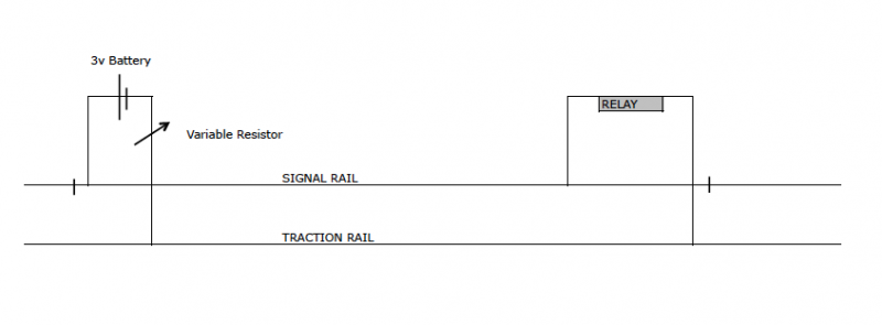 The relay has a Pick Up voltage, that's to say there is a certain voltage level which will cause the relay to energise. (let's assume 0.8v) The resistor is used to adjust the voltage so that the relay is just energised (Probably 25% above it's pick up value). Lets say 1.0v When a train comes along it's wheels cause a short circuit and "shunt" the voltage away from the relay. The voltage measured at the relay will be zero and the relay will drop. FF Post has attachments. Log in to view them. Last edited: 20/12/2011 at 00:23 by Firefly Log in to reply The following user said thank you: Steamer |
| Re: Differences between types of track circuits? 20/12/2011 at 00:38 #25841 | |
|
Firefly
521 posts |
With and Without a train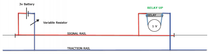 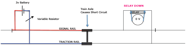 FF Post has attachments. Log in to view them. Last edited: 20/12/2011 at 00:52 by Firefly Log in to reply The following users said thank you: Prof Jolly, Steamer |